Reliable Plastic Injection Molding Manufacturer

During 10 years of development, we have gained a lot of factory resources. They often make relatively large orders and small orders. We provide our customers with injection molding and metal stamping solutions for a variety of industries. So that we can meet the needs of small orders.

We have cooperated with more than 100 customers. They place orders with us to help them communicate and coordinate, and deliver good products to customers to achieve the goal of most factories exporting high-quality products abroad to achieve a win-win situation. At present, we have customers in the automotive field, electronic products, tool products, communication products, medical products and other fields.

Types of Injection Molding Product We Made

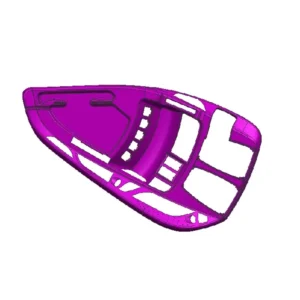
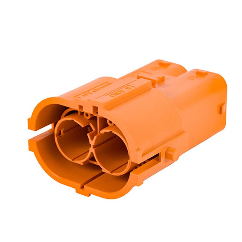
Auto parts injection molding

As a manufacturer of automotive injection molded parts, high component quality and high process stability are the standard requirements of the automotive industry.

Get a free quote
appliance injection molding

Plastic injection molding of hair dryer

Plastic injection molding of hair dryer on the Premise of Meeting Product Performance, Materials With Lower Processing Energy Consumption Should be Given Priority.

Get a free quote
Medical Injection Molding Product

Medical Injection Molding Product

Producing High-quality Products at one Time and Reducing the Defective Rate is the Biggest Energy Saving.

Get a free quote

Get Your Custom Injection Molding Products

Sing oi is a trusted Injection Molding Products manufacturer with years of experience in creating high-quality Injection Molding solutions for various industries. Here are your custom selections:

Get A free quote

Plastic Injection Molding Manufacturing Process

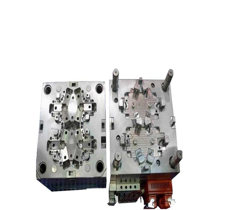
1)Mold closing: The machine starts when the left and right molds are closed together.;

2)filling: starting from the time when the mold is closed and injection molding started, until the mold cavity is filled to approximately 95%:

3)Pressure holding: The function of the pressure holding stage is to continuously apply pressure, compact the melt, and increase the density of the plastic (densification).

4)Cooling: Because molded plastic products can only be solidified by cooling to a certain rigidity.

5)Mold opening: Mold opening is a step of injection molding, although the product has been cold-set.

GET A FREE QUOTE
paper box manufacturing process

Plastic Injection Molding Design Details

plastic molding company

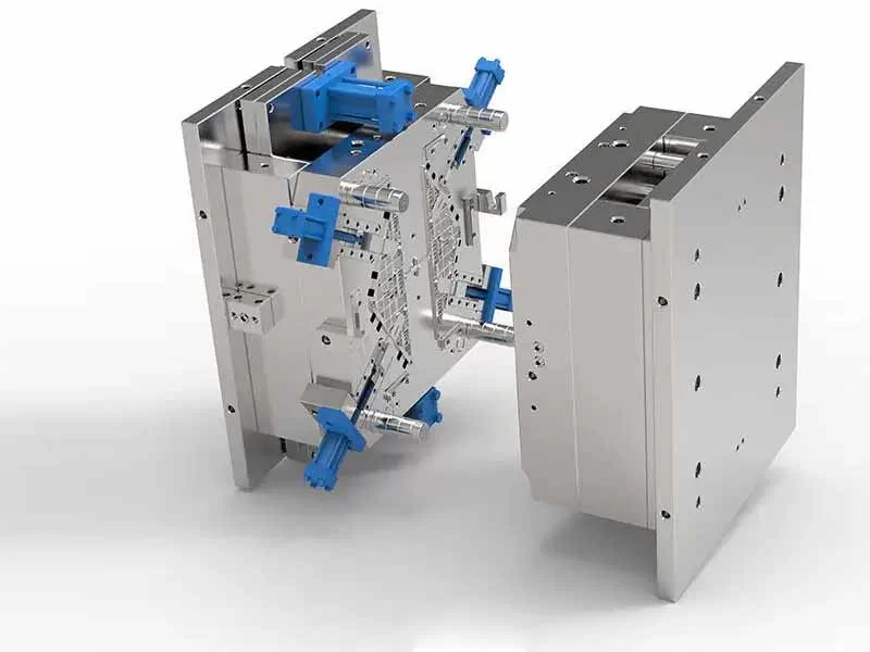
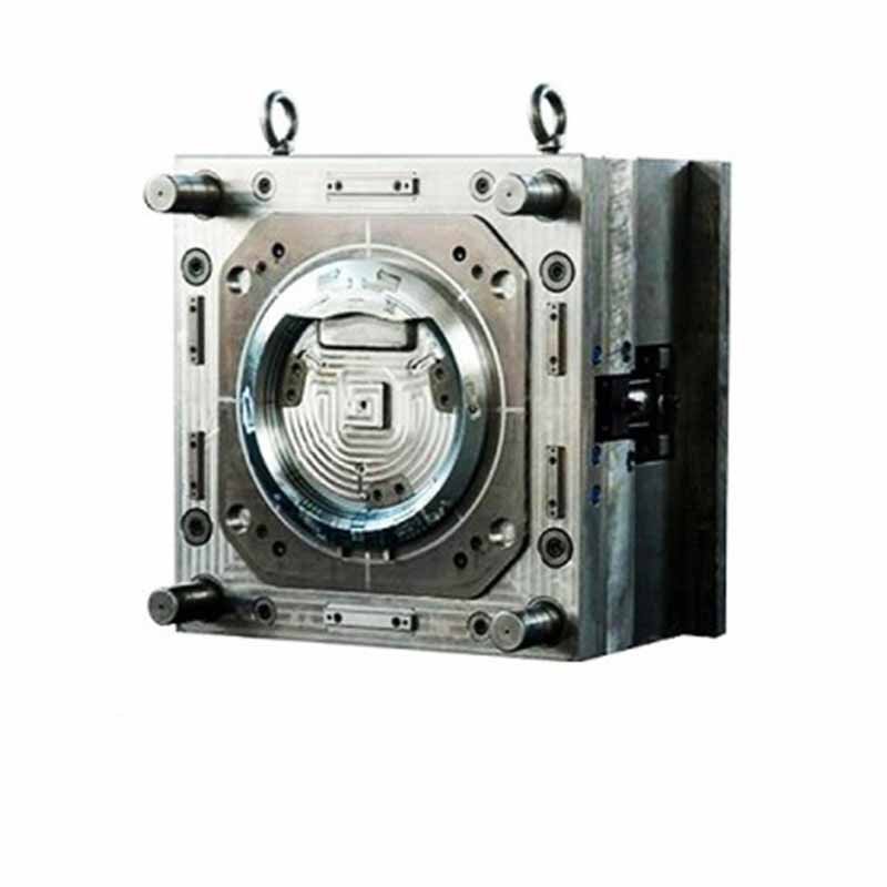
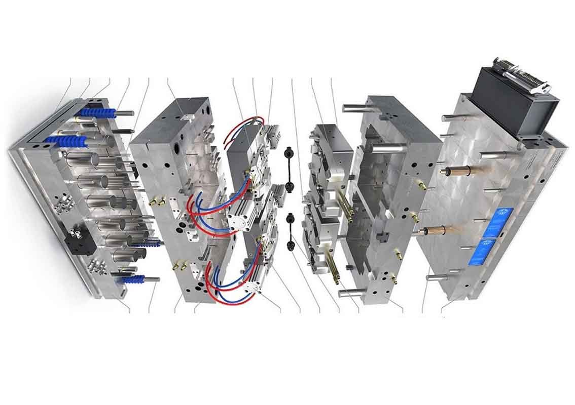
Die casting mould components include the following:

  • Molding System: This determines the shape of the die-casting cavity as the moving core closes. And it relates directly to the core, insert pin, sliders, cavity, and inserts.
  • Mold Base System: Frames and steel plates are the die-casting molds base system’s primary components. It’s where the mold of the die-casting machine can be installed, combined with different mold components.
  • Runner System: This die-casting and pressure chamber part is linked to the runner system. Its system components are a sprue, an inner gate, a runner, etc.
  • Ejection System: Removing components from the mold is the function of this system. Its aspects include returned, ejection parts, and guiding.
GET A FREE QUOTE

Plastic injection molding Benefits

Plastic injection molding offers numerous advantages for manufacturers across various industries. Understanding these benefits can help businesses leverage this technology effectively.
  •  Wide Range of Materials:Versatility in material selection, including engineering-grade plastics, thermoplastics, and elastomers.Tailored material properties to meet specific product requirements.
  • Cost-Effectiveness:Economical for large-scale production runs due to reduced per-unit costs.Minimal waste through efficient material usage and recycling capabilities.

  • Fast Production Cycles:Rapid prototyping and short lead times from design to production.Quick tooling setup and efficient manufacturing processes.

  • High Efficiency and Precision:Injection molding allows for high-volume production with consistent quality and precision.Complex and intricate shapes can be produced with minimal post-processing.

GET A FREE QUOTE
plastic injection molding companies

Plastic Injection Molding Manufacturer Application

Our manufacturing base in China serves world-renowned manufacturers from a variety of industries, including the development, manufacturing and production of plastic products for the power tools, home appliances, home security, industrial electrical and electronics, aerospace, medical devices and gaming industries. Large-scale production.

Why Choose Us as Plastic Injection Molding Supplier

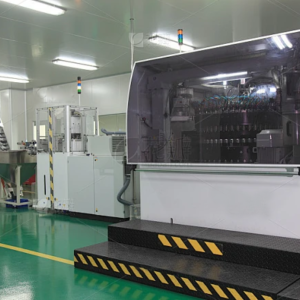
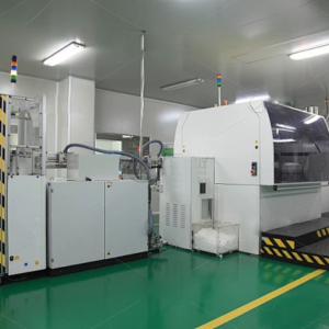
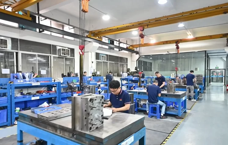
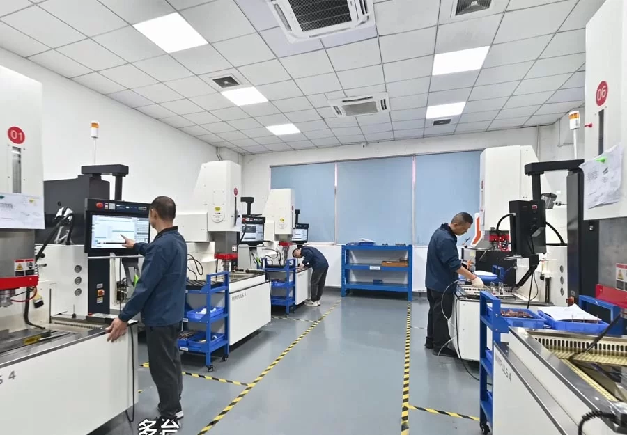
Our Plastic Injection Molding Factory

What Our Other Customers Say About Us

We are very satisfied with this wayofworking by focusingon ourcompany’s needs and providing comprehensive
serices.

Mark Jance / ergotron

P&G has been worked with thismanufacturersince 2015. This supplier cansurprise us through their bestqualitycompetitive price, fast delivery! Reliable all thetime!

John Wilson / P&G

Spectrum Brands Holdings, a member ofthe Russel 1000index, is a global consumerproducts company offering abroad porfoio ofleading brandsfocused on drivnginnovalion and provding exceptional customer servce Weare very happy to cooperate with this great company.

Alvin Cullum York / Spectrum Brands

The KATHRElN-Werke KG is the world’s largest antennaproducingenterprise with the longest standing tradition ofall marketing competitors,and a leading high techtelecommunication company, We just started workingtogetherand everything went very smoothly. This is verygood.

Speiser / Kathrein

After-Sales Support

1. Product Quality Services

It is commendable places such a high priority on product quality. Ensuring that each production process, from manufacturing to packaging, undergoes special quality inspections is crucial for meeting customer specifications and international standards. This commitment to quality not only builds trust with your customers but also contributes to the long-term success of business.

2. Real-Time Online Support 

Real-time online 7*24 hours online service.

3. Design Capabilities

Our engineering design team participates in the mold design and development of customers throughout the process, assisting customers to quickly confirm and complete the design structure drawing, from the careful selection of materials in the early stage, to the later hardware, plastic mold production and proofing, and then to the production stage.

4. Our strategy

sing oi provides different solutions to meet various industries.From small orders of 100 to orders of 1 million products, you can rest assured that we provide everything you need.

Our Partner

Ready to Get the Perfect Product?

Contact Us to Get A Free Consultation

Plastic Injection Molding FAQs

Injection Molding by Material

ABS, PC, LCP, PE, PET, PEI, LDPE, HDPE and PP, POM, PC+ABS, TPU, PEEK, HIPS, PMMA,NYLON

The thinner the wall product is, the farther away from the gate, the more important it is to open the venting groove. In addition, for small parts or precision parts, the opening of the venting groove should also be taken seriously, because in addition to avoiding surface burns and insufficient injection volume of the product, it can also eliminate various defects of the product and reduce mold pollution.

The venting groove has two main functions: one is to remove the air in the mold cavity when injecting molten material; the other is to remove various gases generated by the material during heating.

So, how can the venting of the mold cavity be considered sufficient? Generally speaking, if the molten material is injected at the highest injection rate and no scorch marks are left on the product, it can be considered that the venting in the mold cavity is sufficient.

1. Venting method
There are many ways to vent the mold cavity, but each method must ensure that: while venting, the venting groove should be designed to prevent the material from overflowing into the groove; secondly, it must prevent clogging. Therefore, the height of the exhaust groove part that is more than 6-12mm long, measured from the inner surface of the mold cavity to the outer edge of the mold cavity, should be enlarged by about 0.25-0.4mm.

In addition, too many exhaust grooves are harmful. Because if the clamping pressure acting on the part of the mold cavity parting surface without exhaust grooves is very large, it is easy to cause cold flow or cracking of the mold cavity material, which is very dangerous.

In addition to exhausting the mold cavity on the parting surface, the purpose of exhaust can also be achieved by setting exhaust grooves at the end of the material flow of the pouring system and leaving gaps around the ejector rod. Because if the depth, width and position of the exhaust groove are not selected appropriately, the flash burrs will affect the beauty and precision of the product. Therefore, the size of the above gap is limited to prevent flash around the ejector rod.

It should be noted that when venting parts such as gears, even the smallest flash may not be desirable. Gear parts are best vented in the following ways:

(1) Thoroughly remove the gas in the flow channel;

(2) Shot peening the mating surface of the parting surface with silicon carbide abrasive with a particle size of 200.

In addition, a venting groove is opened at the end of the material flow of the pouring system, mainly referring to the venting groove at the end of the branch channel. Its width should be equal to the width of the branch channel, and its height varies depending on the material.

2. Design method
For product molds with complex geometric shapes, it is best to determine the opening of the venting groove after several trial molds. The biggest disadvantage of the overall structural form in the mold structure design is poor venting.

For the overall mold cavity core, there are several venting methods:

(1) Use the groove or insert installation part of the cavity;

(2) Use the insert joint on the side;

(3) Make it into a spiral shape locally;

(4) Install a slotted slat core and open a process hole in the longitudinal position.

When venting is extremely difficult, use an inlay structure. If it is difficult to open the exhaust groove in some dead corners of the mold, first of all, the mold should be appropriately changed to inlay processing without affecting the appearance and precision of the product. This is not only conducive to processing the exhaust groove, but sometimes it can also improve the original processing difficulty and facilitate maintenance.

3. Design size of exhaust groove
The exhaust of thermosetting materials is more important than that of thermoplastic materials.

First of all, the runners in front of the gate should be exhausted. The width of the exhaust groove should be equal to the width of the runner and the height should be 0.12mm. The cavity should be exhausted all around, and each exhaust groove should be 25mm apart, 6.5mm wide, and 0.075-0.16mm high, depending on the fluidity of the material. Softer materials should take lower values.

The ejector rod should be enlarged as much as possible, and in most cases, 3-4 planes with a height of 0.05mm should be ground on the cylindrical surface of the ejector rod, and the grinding mark direction should be along the length of the ejector rod. Grinding should be carried out with a finer grinding wheel. The end face of the ejector rod should be ground with a chamfer of 0.12mm, so that if flash is formed, it will adhere to the part.

4. Conclusion
Properly opening the exhaust groove can greatly reduce the injection pressure, injection time, holding time and clamping pressure, making the molding of plastic parts easier, thereby improving production efficiency, reducing production costs, and reducing the energy consumption of the machine.

In fact, it is not necessary to exhaust through the exhaust groove. There are several other ways to exhaust:

(1) Exhaust through the exhaust groove
For molds for molding large and medium-sized plastic parts, the amount of gas to be exhausted is large, and the exhaust groove should usually be opened. The exhaust groove is usually opened on the side of the concave mold on the parting surface. The position of the exhaust groove is preferably at the end of the melt flow, and the size of the exhaust groove is based on the principle that the gas can be discharged smoothly without overflowing. The width of the exhaust groove is generally about 3-5mm, the depth is less than 0.05mm, and the length is generally 0.7-1.0mm.

(2) Venting from parting surface
For small molds, the gap between the parting surface can be used for venting, but the parting surface must be located at the end of the melt flow.

(3) Venting from the gap between the assembled parts
For combined concave molds or cavities, the gap between the assembled parts can be used for venting.

(4) Venting from the gap between the push rod and the mold plate or core, or the gap between the push rod and the mold plate can be intentionally increased.

(5) Venting from powdered unsintered alloy blocks
Powdered unsintered alloy is a material made by sintering spherical granular alloys. It has poor strength but a loose texture that allows gas to pass through. Placing a piece of such alloy at the location where venting is required can meet the venting requirements, but the diameter of the bottom vent hole should not be too large to prevent it from being squeezed and deformed by the cavity pressure.

(6) Venting from exhaust wells
A hole is set on the outside of the plastic melt confluence to allow gas to be discharged into it, which can also achieve good venting effect.

(7) Forced exhaust
In the closed gas area, an exhaust rod is installed. This method has a good exhaust effect, but it will leave traces of the rod on the plastic part. Therefore, the exhaust rod should be installed in a hidden place of the plastic part.

Gas is often generated in injection molds, which may be related to the following points:
There is air in the pouring system and the mold cavity. Some raw materials contain moisture that has not been dried and removed. They will vaporize into water vapor at high temperatures. Due to the high temperature during injection molding, some unstable plastics will decompose and produce gas. Some additives in the plastic raw materials volatilize or react with each other to generate gas. At the same time, the cause of poor exhaust needs to be found as soon as possible. Poor exhaust of injection molds also brings troubles to plastic parts. The main manifestations are as follows:

During the injection molding process, the melt will replace the gas in the cavity. If the gas is not discharged in time, it will cause difficulty in melt filling, resulting in insufficient injection volume and failure to fill the cavity. Poorly discharged gas will form high pressure in the cavity, and penetrate into the interior of the plastic under a certain degree of compression, causing quality defects such as voids, pores, loose organization and silver streaks. Because the gas is highly compressed, the temperature in the cavity rises sharply, which in turn causes the surrounding melt to decompose and burn, causing local carbonization and burning of the plastic part. It mainly occurs at the confluence of two melts and the gate flange. Poor gas discharge makes the melt entering each cavity at different speeds, so it is easy to form flow marks and fusion marks, and reduce the mechanical properties of the plastic part. Due to the obstruction of gas in the cavity, the filling speed will be reduced, affecting the molding cycle and reducing the tax collection efficiency.

Distribution of bubbles in plastic parts:
The bubbles generated by the accumulation of air in the cavity are often distributed in the part opposite to the gate. The bubbles generated by the decomposition or chemical reaction of the plastic raw material are distributed along the thickness of the plastic part. The bubbles generated by the vaporization of residual water in the plastic raw material are irregularly distributed throughout the plastic part.

Yes, we can provide custom sizes for our plastic Injection Molding. Our team of experts can work closely with customers to determine the appropriate dimensions based on their unique needs.

Mold temperature is the most important variable in injection molding – no matter what plastic is injected, it must ensure that the mold surface is basically wet. A hot mold surface keeps the plastic surface liquid long enough to build pressure in the cavity. If the cavity is filled and the cavity pressure can press the soft plastic against the metal before the frozen skin hardens, then the cavity surface temperature is high.

On the other hand, if the plastic entering the cavity under low pressure pauses, no matter how short the time, then its slight contact with the metal will cause stains, sometimes called gate stains.

For each plastic and plastic part, there is a limit to the mold surface temperature, exceeding which one or more undesirable effects may occur (for example: the component can overflow with flash). Higher mold temperature means less flow resistance.

On many injection molding machines, this naturally means faster flow through the gate and cavity, and because the injection flow control valve used does not correct for this change, faster filling will cause higher effective pressures in the gate and cavity.

Flash may be caused. Because the hotter model does not freeze the plastic that enters the flash area before high pressure is built, the melt can flash around the ejector pin and overflow into the parting line gap. This indicates that good injection rate control is required, and some modern flow control programmers do provide this.

In general, increasing mold temperature will reduce the plastic condensation layer in the cavity, making it easier for the molten material to flow in the cavity, resulting in a larger part weight and better surface quality. At the same time, the tensile strength of the part will increase with the increase in mold temperature.

Mold insulation methods

Many molds, especially engineering thermoplastics, operate at relatively high temperatures, such as 80 degrees Celsius or 176 degrees Fahrenheit. If the mold is not insulated, the heat lost to the air and injection molding machine can easily be as much as that lost to the shot cylinder.

Therefore, the mold frame plate should be insulated, and if possible, the surface of the mold should be insulated. If you are considering using a hot runner mold, try to reduce the heat exchange between the hot runner part and the cooled injection molded part. This method can reduce energy loss and preheating time.

Weld lines are the most common defects in injection molded products. Except for a few injection molded parts with very simple geometric shapes, they occur on most injection molded parts (usually in the shape of a line or a V-shaped groove), especially large and complex products that require multi-gate molds and inserts.

Weld lines not only affect the appearance quality of plastic parts, but also affect the mechanical properties of plastic parts, such as impact strength, tensile strength, elongation at break, etc. to varying degrees. In addition, weld lines also have a serious impact on product design and the life of plastic parts. Therefore, they should be avoided or improved as much as possible.

The main reasons for weld marks are: when the molten plastic encounters inserts, holes, areas with discontinuous flow rates or areas where the filling material flow is interrupted in the cavity, multiple melts converge; when the gate injection filling occurs, the material cannot be completely fused.

Causes and solutions for weld marks:

1. The temperature is too low
The diversion and convergence performance of low-temperature melts is poor, and weld marks are easily formed. If weld fine lines appear on the inner and outer surfaces of the plastic part at the same location, it is often due to poor welding caused by too low material temperature. In this regard, the barrel and nozzle temperature can be appropriately increased or the injection cycle can be extended to promote the material temperature to rise. At the same time, the amount of cooling water passing through the mold should be controlled, and the mold temperature should be appropriately increased.

In general, the strength of the weld mark of the plastic part is poor. If the corresponding part of the mold where the weld mark is generated is locally heated and the local temperature of the welded part of the molded part is increased, the strength of the welded part of the plastic part can often be improved.

If the low-temperature molding process must be used due to special needs, the injection speed and injection pressure can be appropriately increased to improve the convergence performance of the melt. A small amount of lubricant can also be added to the raw material formula to improve the flow performance of the melt.

2. Mold defects
The structural parameters of the mold casting system have a great influence on the welding condition of the flow material, because poor welding is mainly caused by the diversion and convergence of the melt. Therefore, the gate form with less diversion should be used as much as possible and the gate position should be reasonably selected to avoid inconsistent filling rate and interruption of filling material flow. Under possible conditions, a one-point gate should be used, because this gate does not produce multiple streams, the melt will not converge from two directions, and it is easy to avoid welding marks.

If there are too many or too small gates in the casting system of the mold, the multi-gate positioning is incorrect or the distance from the gate to the flow material welding point is too large, the main flow channel inlet of the casting system and the flow channel section of the diversion channel are too small, resulting in too large material flow resistance, which will cause poor welding and produce more obvious welding marks on the surface of the plastic part. In this regard, the number of gates should be reduced as much as possible, the gate position should be set reasonably, the gate section should be increased, the auxiliary flow channel should be set, and the main flow channel and diversion channel diameter should be expanded.

In order to prevent low-temperature molten material from being injected into the mold cavity and causing weld marks, a cold material hole should be set in the mold while increasing the mold temperature.

In addition, the location where the weld marks of plastic parts are produced often produces flash due to high-pressure mold filling, and the weld marks will not produce shrinkage holes after such flashes are produced. Therefore, such flashes are often not used as troubleshooting, but a very shallow groove is opened at the location where the flash is produced on the mold to transfer the weld marks on the plastic parts to the additional flash winglets, and then the winglets are removed after the plastic parts are formed. This is also a common method for troubleshooting weld mark faults.

3. Poor mold exhaust
When the weld line of the molten material coincides with the mold joint line or caulking of the mold, the air squeezed by multiple streams of flow materials in the mold cavity can be discharged from the mold joint gap or caulking;
But when the weld line does not coincide with the mold joint line or caulking, and the exhaust hole is not set properly, the residual air squeezed by the flow materials in the mold cavity cannot be discharged, and the bubbles are strongly squeezed under high pressure, and the body gradually becomes smaller and finally compressed into a point. Since the molecular kinetic energy of the compressed air is converted into heat energy under high pressure, the temperature at the melt confluence point increases. When its temperature is equal to or slightly higher than the decomposition temperature of the raw material, yellow spots appear at the weld point. If its temperature is much higher than the decomposition temperature of the raw material, black spots appear at the weld point.
Generally speaking, such spots appearing near the weld mark on the surface of the plastic part always appear repeatedly at the same position, and the parts that appear always appear regularly at the confluence point. During operation, such spots should not be mistaken for impurity spots. The main reason for such spots is poor mold exhaust, which is a carbonization point formed after the high-temperature decomposition of the molten material.
After this type of failure occurs, first check whether the mold vent is blocked by solidified materials or other objects of the melt, and whether there are foreign objects at the gate. If carbonization points still appear after the blockage is removed, add vents at the mold confluence point. You can also accelerate the confluence of materials by repositioning the gate or appropriately reducing the mechanical force and increasing the venting gap. In terms of process operation, auxiliary measures such as lowering the material temperature and mold temperature, shortening the high-pressure injection time, and reducing the injection pressure can also be taken.

4. Improper use of release agent
Excessive use of release agent or incorrect selection of varieties will cause welding marks on the surface of plastic parts. In injection molding, a small amount of release agent is generally applied evenly only on parts such as threads that are difficult to demold. In principle, the amount of release agent should be minimized.

The selection of various release agents must be determined based on molding conditions, plastic part shape, and raw material varieties. For example, pure zinc stearate can be used for various plastics except polyamide and transparent plastics, but it can be used for polyamide and transparent plastics after mixing with oil. For example, silicone oil toluene solution can be used for various plastics, and it can be used for a long time after being applied once, but it needs to be heated and dried after application, and its use is relatively complicated.

5. Unreasonable plastic structure design
If the wall thickness of the plastic part is designed to be too thin, the thickness difference is too large, and there are too many inserts, it will cause poor welding. When thin-walled parts are molded, defects are easy to occur because the molten material solidifies too quickly, and the molten material always converges at the thin wall during the mold filling process to form a weld mark. Once a weld mark is generated at the thin wall, the strength of the plastic part will be reduced, affecting the performance.

Therefore, when designing the shape structure of the plastic part, it should be ensured that the thinnest part of the plastic part must be greater than the minimum wall thickness allowed during molding. In addition, the use of inserts should be minimized and the wall thickness should be as consistent as possible.

6. Other reasons
When the moisture or volatile content of the raw materials used is too high, the oil stains in the mold are not cleaned, there is cold material in the mold cavity or the fiber filler in the melt is poorly distributed, the mold cooling system is not designed reasonably, the melt solidifies too quickly, the insert temperature is too low, the nozzle hole is too small, the plasticizing capacity of the injection molding machine is insufficient, and the pressure loss in the injection molding machine barrel is too large, it will lead to different degrees of poor welding.

In this regard, during the operation process, according to different situations, measures such as pre-drying of raw materials, regular cleaning of molds, changing the setting of mold cooling water channels, controlling the flow of cooling water, increasing the insert temperature, replacing nozzles with larger apertures, and using larger injection molding machines should be taken to solve the problem.

Contact Us

    Blogs About Plastic Injection Molding Manufacturing

    Causes and Analysis of Whitening of Injection Molds

    During the injection molding process, any product may have defective products. It is normal to [...]

    Methods to Improve the Quality of Injection Molding

    The appearance of light spots in the mold is a common quality problem in injection [...]

    Injection Molding Supplier Analyzes Unbalanced Gating System

    Charger shell manufacturers focus on the production of plastic products and have an in-depth understanding [...]

    Charger Shell Mold Design

    Key points of mold design for charger shell manufacturers After receiving an order, the Charger [...]

    Charger Shell Manufacturers Analyze the Key Factors of Plastic Molding

    In order to improve competitiveness, charger shell manufacturers must continuously optimize the injection molding process [...]

    Importance of Demoulding Slope of Charger Shell

    Many Charger injection molding manufacturers focus on shell injection molding of mobile phone chargers, computer [...]

    Wide application and advantages of PBT materials in injection molding

    Wide application and advantages of PBT materials in injection molding The quality of injection molding [...]

    Process Requirements of PA Materials in Injection Molding Plants

    Process requirements of PA materials in injection molding plants PA (polyamide) is a thermoplastic commonly [...]