
It seems that some new machines have injection speed issues because machine manufacturers confuse processors with controllers that are more complex and less user-friendly than they need to be. There are hundreds of variables that can affect your process, and the last thing you need is for the quirks of a machine controller to disrupt your day. Machine controllers play a major role in the production of quality parts. There are subtle but significant differences between controllers; in order to make the same part on different molding machines, processors must be aware of these variations. So let’s take a closer look at how machine manufacturers differ in holding functions.
All machines follow a general injection sequence where the screw starts at the “shot size” and injects the molten plastic at one or more speeds into a preset transfer position. The moment the screw reaches this transfer or cutoff position, the machine switches from the first (injection) stage to the second (pack and hold) stage. Different machine manufacturers have different options for what happens during the pack and hold process. Some offer time at pressure, others offer pressure and time stages. Others offer pressure, time, ramp time, and speed stages. Unfortunately, this complicates the injection molding process, and in my opinion, some options are very detrimental to consistent parts. Wondering why?
Machine builders are eager to come up with more complex processing modes, but rarely do they verify them in production with cavity pressure monitoring.
Since there are many options for packing and holding, depending on the machine and manufacturer, we will set constant parameters and review seven variations or options. To describe these possible options, we will use the following set (constant) conditions:
1. First Stage or Injection: All machines are set to inject (first stage) and transfer to second stage at one location or volume, in this case using 1 second ± 0.04 seconds for first stage injection. Using the same mold on each machine, we found that the pressure at the time of transfer was 16,000 psi of “plastic” pressure. For the purposes of this discussion, all pressures will be expressed in “plastic” (not hydraulic) numbers. This makes it easier to compare motors to hydraulic machines. Also, if you want the same part, when you transfer a mold from one machine to another, you must copy the plastic conditions rather than the machine settings. Although hydraulic is popular among processors, it does not transfer between machines due to different intensification ratios.
2. Second Stage (Pack/Hold): Here we will set two pack pressures: 10,000 psi for 3 seconds, then 8000 psi for 5 seconds. Again, all pressures are “plastic” and not hydraulic. The following assumptions attempt to demonstrate the differences that may exist between different machines within the second stage:
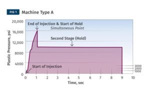
Machine Type A: This machine allows the processor to set the time and pressure once for the second stage pack or hold. For example, the pressure is 10,000 psi for 8 seconds. The pressure changes from a transfer pressure of 16,000 psi to 10,000 psi and holds that pressure for 8 seconds.
Machine Type B: The machine allows the processor to set the pack pressures and associated times for two or more stages. For example, 10,000 psi for 3 seconds plus 8000 psi for 5 seconds for a total hold time of 8 seconds. There are several possible hold responses depending on the machine manufacturer:
Machine Manufacturer 1: Pressure drops from a first stage transfer pressure of 16,000 psi to 10,000 psi as quickly as possible. At the end of the 3 seconds, pressure is immediately dropped to 8000 psi for 5 seconds. See the plot of plastic pressure vs. time in Figure 2.
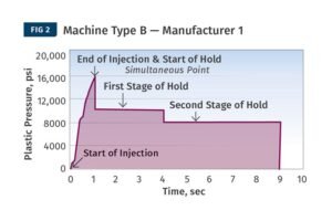
This machine allows the processor to set two or more stages of hold pressure and associated times. Here, pressure drops from a first stage transfer pressure of 16,000 psi to 10,000 psi as quickly as possible. At the end of the programmed 3 seconds, pressure is immediately dropped to 8000 psi for 5 seconds.
Machine Manufacturer 2: The machine takes 3 seconds to drop from a transfer pressure of 16,000 psi to 10,000 psi, then quickly ramps up to 8000 psi and holds for 5 seconds. In this case, the first time is actually the ramp time to the set pressure, not the time to the set pressure. See Figure 3 for a graph of plastic pressure vs. time.
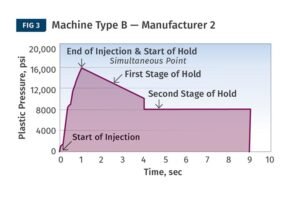
Here, the machine takes 3 seconds to ramp down from a 16,000 psi delivery pressure to 10,000 psi, then quickly ramps up to 8000 psi and holds for 5 seconds. The first time is actually the ramp time to the set pressure, not the time at the set pressure.
Machine Builder 3: The machine takes 3 seconds to ramp down from a 16,000 psi delivery pressure to the set 10,000 psi holding pressure, then takes 5 seconds to ramp down from 10,000 psi to 8000 psi. Both hold times are “ramp times,” not times at the set pressure. See Figure 4 for a graph of plastic pressure vs. time.
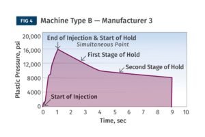
The machine takes 3 seconds to ramp down from a transfer pressure of 16,000 psi to a set hold pressure of 10,000 psi, and then 5 seconds to ramp down from 10,000 psi to 8000 psi. Both hold times are “ramp times” rather than times at the set pressure.
Type C Machines: These machines allow the processor to set two or more stages of hold pressure, time, and speed. Using the same pressures and times as above, we now set the first hold stage speed to 35 mm/sec and the second hold stage speed to 15 mm/sec.
Machine Manufacturer 4: Only the first stage hold has a speed setting, pressure dominates in both stages. Pressure ramps down from a transfer pressure of 16,000 psi to 10,000 psi at 35 mm/sec until it reaches a hold pressure of 10,000 psi. At this point speed control is lost (pressure limited) and the machine holds a constant 10,000 psi for the remainder of the 3 seconds. At the end of the 3 seconds, the pressure drops rapidly to 8000 psi and is held for 5 seconds. For a plot of pressure vs. time,
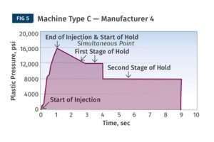
Here, pressure dominates both stages. Pressure drops from a delivery pressure of 16,000 psi to 10,000 psi at a rate of 35 mm/sec until a holding pressure of 10,000 psi is reached. At this point speed control is lost (pressure limited) and the machine holds a constant 10,000 psi for the remainder of the 3 seconds.
Machine Manufacturer 5: Pressure Override Set the speed for both holding stages. Pressure drops from a delivery pressure of 16,000 psi to 10,000 psi at a rate of 35 mm/sec until the pressure driving the screw forward reaches 10,000 psi. At 10,000 psi, speed control is lost (pressure limited) and the machine holds a constant 10,000 psi for the remainder of the 3 seconds. At the end of the 3 seconds, the pressure is ramped up to 8000 psi at 15 mm/sec until the pressure reaches 8000 psi and remains at 8000 psi for the remainder of the preset 5 second hold. Again, this step is pressure limited and I doubt there is any speed control when the hold pressure changes from 10,000 psi to 8000 psi. A plot of pressure vs. time is shown in Figure 6.
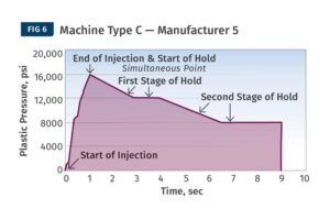
The pressure override sets the speed for both hold stages. The pressure is ramped down from the 16,000 psi delivery pressure to 10,000 psi at 35 mm/sec until the pressure driving the screw forward reaches 10,000 psi. At 10,000 psi, speed control is lost (pressure limited) and the machine maintains a constant 10,000 psi for any remaining time in the 3 seconds.
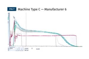
Machine Manufacturer 6: Speed exceeds set pressure. Pressure is ramped down from the 16,000 psi delivered pressure and will be driven by speed control to whatever pressure is required to achieve a speed of 35 mm/sec for 3 seconds. Speed exceeds pressure setting and pressure may not be 10,000 psi. At the end of the 3 seconds, the machine will run at 15 mm/sec for 5 seconds. Again, speed control overrides pressure setting. Figure 7 shows several shots under these conditions (plastic pressure in red, cavity pressure in green; different scales). As can be seen, after hours of experimentation, I tried to get process consistency without success.
Speed Over Set Pressure. The graph shows several shots under these conditions (plastic pressure in red, cavity pressure in green; different scales). After hours of experimentation, attempts to get process consistency without success.
Confused? Me too. This is more complicated than it should be. Processors have plenty of processing power. Machine builders are eager to come up with more complex processing modes, but rarely test them in production with cavity pressure monitoring. As new and faster computers become available, programmers with good intentions are adding features (such as packing speed) that hinder product consistency.
] Bottom line: Many machine builders make controls more complex than they need to be and less user friendly by adding options of questionable value. Speed control on packing without pressure limiting or pressure cutoff is a classic example. For any evaluation of a machine controller that has a second stage (packing or holding) speed control, it is best to have cavity pressure sensing.